The Use of a Residual Gas Analyzer (RGA) to Determine Differences in Graphite and All-metal Hot Zone Vacuum Operation
Introduction
This paper will summarize the following:
- What is a Residual Gas Analyzer (RGA) and how does it work?
- What are the residual gases when analyzing a vacuum furnace in various conditions?
- What are the residual gases when comparing an all-metal to graphite insulated hot zone?
- What are the energy and maintenance comparisons of all-metal to graphite insulation?
What is a Residual Gas Analyzer (RGA)?
 The RGA is a type of mass spectrometer that can detect atomic mass ranges from 1 to 300. However, it typically looks for atomic masses from 1 to 50.
The RGA can sample atmospheric pressures down to the 5×10-12 Torr range but normally samples at the 1×10⁻⁶ Torr vacuum level for our equipment.
The RGA provides a semi-quantitative measurement of the remaining gases in a vacuum system. It does not provide absolute values but compares relative amounts of residual gases that remain in the system.
RGAs can also be used as sensitive helium leak detectors. With vacuum systems pumped down to lower than 10-5 Torr—checking of the integrity of the vacuum seals and the quality of the vacuum—air leaks, virtual leaks and other contaminants at low levels may be detected before a process is initiated.
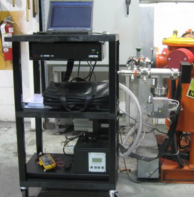
Components of a Typical RGA Set-Up
A proper set-up for an RGA is to position the sensor to an extension from the vacuum chamber with a valve initially isolating the sensor from the chamber. Providing the vacuum to the sensor would be a turbo molecular pump backed by an oil sealed, rotary vein pump.
Initially the valved-off sensor connection is pumped down to 5×10⁻⁵ Torr or better prior to opening the valve to the main chamber.
The RGA does not detect solids, only gases with less than 100 AMU.

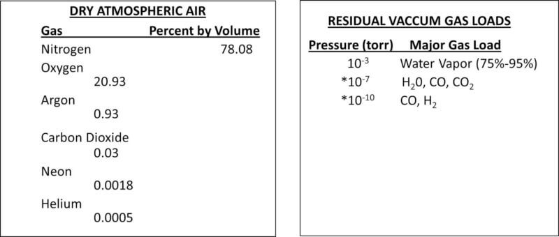
Atmosphere Versus Vacuum Molecular Comparison

The above two figures illustrate the difference in a typical chamber at atmospheric pressure and a chamber under deep vacuum. The “perfect vacuum” does not exist. Trace amounts of gases are always present in a vacuum chamber or system.
A typical atmosphere would have approximately 1×10²⁰ molecules per cubic centimeter while a typical high vacuum would have approximately 1×10¹⁰ molecules per cubic centimeter.
The RGA analyzes the residual gas molecules remaining in the vacuum system which can include water vapor.
The following Period Table of Elements reflects the various atomic mass numbers for the various elements and gases to be discussed.

Comparing Types of Gases in Air and Vacuum
The following charts illustrate the difference in gases of atmospheric air and high vacuum:
Typical RGA Scans of a Basic Vacuum Furnace
We have analyzed a typical vacuum furnace that has been pumped down to the 10-4 Torr range and have shown the residual gases on both Log and Linear curves on the two charts that follow:
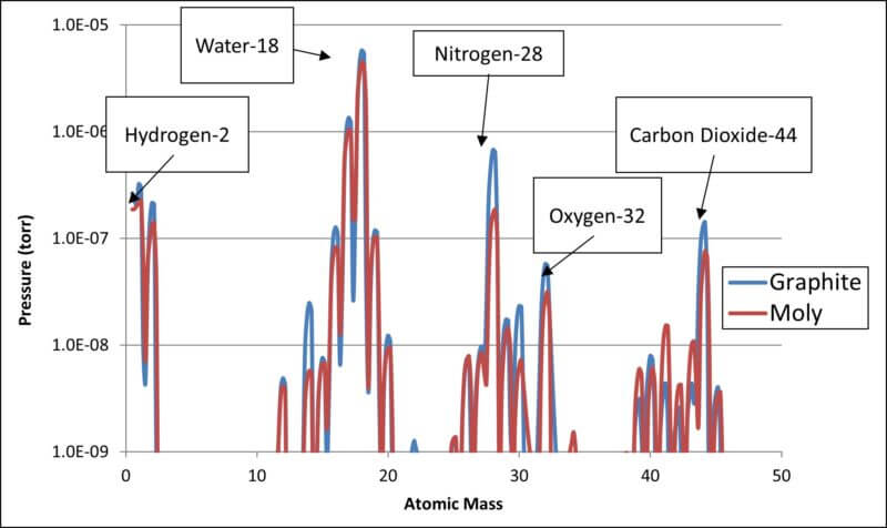
- RGA Log Scale Chart of Residual Gases
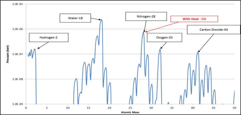
Please note that on the above chart, water has an atomic mass of 18. Since water is H2O, we have Hydrogen = 1 times 2 = 2 plus Oxygen = 16 for a total of 18.
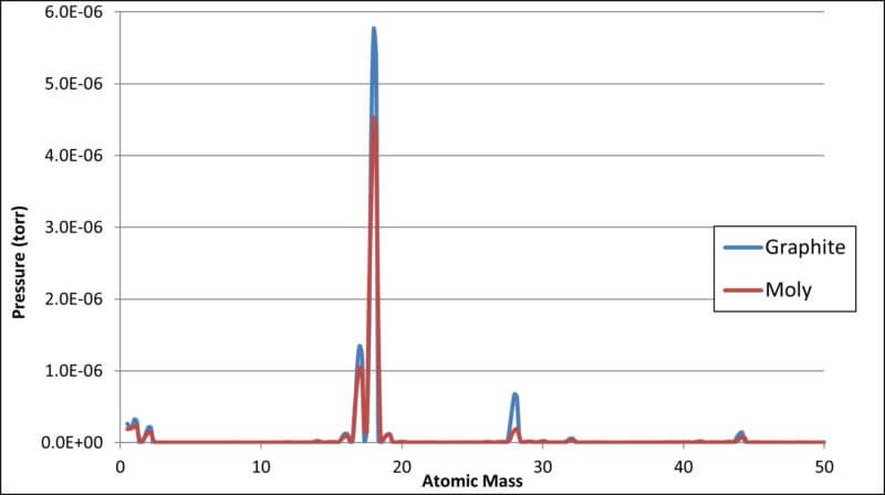
- RGA linear Scale Chart of Residual Gases
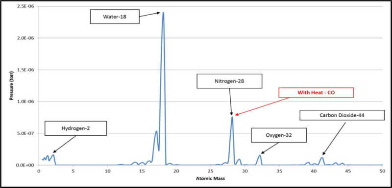
As shown above, all the residual gases as related to the residual water vapor are better reflected in the log scale chart while the linear scale highlights water as the serious major player.
Illustration of Two types of Vacuum Furnace leaks
Air Leak
A RGA can be used to help determine what type of leak is occurring in a vacuum furnace. Most leaks are some type of air leak due to bad seals or joints. An acceptable furnace leak is normally less than 20 microns per hour while a leak rate of greater than 20 microns per hour indicates a more serious problem.
The following chart illustrates the two different RGA plots that reflect the acceptable and unacceptable conditions.

As is shown, with a serious air leak, nitrogen and oxygen (major components of air) are the atomic masses that peak.
Water Leak
Our next chart illustrates the RGA plot of a furnace water leak.
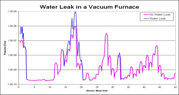
As expected, the highest peak is for our water residual component.
Comparing an All-Metal Hot Zone Furnace Versus a Graphite Hot Zone Furnace
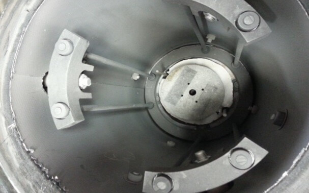
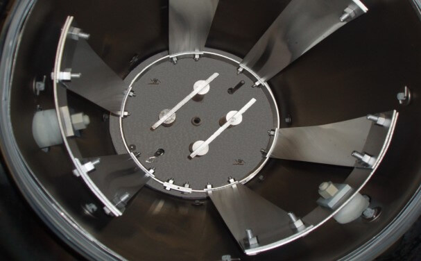
Many vacuum furnace processes require a very deep vacuum and minimal residual carbon gas in order not to contaminate the final product. In order to illustrate the relative residual gases remaining in two different types of insulated furnaces, we selected two of our identical sized lab furnaces for comparison. One had a graphite insulated hot zone with graphite elements awhile the other had an all-metal molybdenum/stainless steel shielded design with molybdenum elements. Photos of both are shown below.
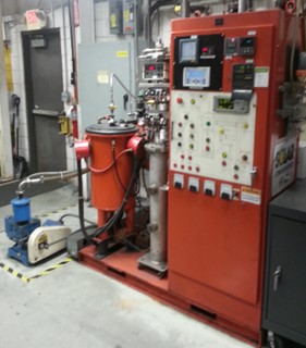
The two furnaces had identical pumping systems with Varian 8” diffusion pumps and hot zones that measured 10” diameter by 18” high.
Prior to proceeding with a RGA analyzes, both furnaces were prepared as follows:
- Bake out furnace at 2250°F for 2 hours and vacuum cool to <125°F.
- Open furnace door for 5 minutes.
- Pump down to 5 x 10⁻⁵
- Ramp at 20°F / minute to 2200°F.
- Hold for 1 hour.
The Ambient Temperature RGA Comparison at 5×10⁻⁵ Torr on a Log scale is shown below. The all-metal is identified as Moly while the insulated design is defined as Graphite.
The results above indicate that air components and carbon are definitely more prevalent in the graphite insulated furnace. This should be expected by the higher surface area of the graphite felt material than the all metal design and its retention of water vapor and air components when the furnace is open and also the graphite carbon molecules contributing to the carbon dioxide residual gas.
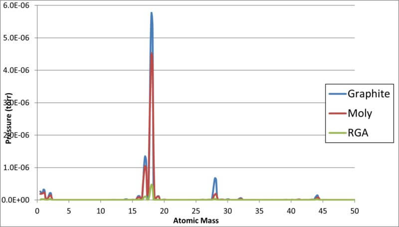
A liner RGA plot of the above ambient temperature tests is shown on our next chart.
Authors: Trevor Jones and Real Fradette