Preventing Eutectic Reactions and Diffusion Bonding in Vacuum Processing
Introduction
This paper explains reactions that can occur during a vacuum processing cycle and different methods of preventing these reactions. We will discuss how eutectic compositions can form while heat treating and how diffusion bonding can be a concern to heat treaters when two dissimilar materials are in close contact with each other in high vacuum at elevated temperatures.
To many people, the term “eutectic” is not well understood. The best way to think of a eutectic is a metallurgical meltdown. A eutectic reaction occurs when two components with different melting points and surfaces free of oxides come in contact with each other in the vacuum furnace. This can create an atomic diffusion. For some materials, when a specific atomic composition is reached, they will melt at a temperature much lower than the melting point of the individual metals. If that temperature is reached or exceeded during the heat treating cycle, melting will occur at the contact points. This is referred to as a eutectic melt.
The most common example of a eutectic reaction is with a tin/lead solder. Tin melts at about 450°F, while lead melts at about 620°F. When they are together as two components, the solder melts at 370°F. That is 80 degrees below where tin melts at and 250 degrees below where lead melts.
Another good example in vacuum heat treating is the titanium/nickel eutectic. In this scenario, titanium melts a little above 3000°F, whereas nickel melts at about 2650°F. If you heat treat them in a vacuum furnace, placing the titanium on a typical heat treat fixture such as a grid or stainless steel basket, the two materials would melt at around 1730°F. This could be a disaster if the technician does not understand the eutectic reaction.
We learned a good lesson on eutectic melting a couple years ago when a clean-up run was performed in one of our furnaces at 2400°F without prior removal of a work grid. The high nickel alloy cast fabricated grid was sitting on molybdenum support rods positioned on the furnace graphite support rails.

A form of a eutectic is diffusion bonding, a reaction that occurs well below the eutectic melting point and must be considered when two or more materials are in direct contact.
Diffusion bonding becomes more acute as the mass of the parts in contact increases. In vacuum brazing, a eutectic reaction can be a desirable formation when joining two pieces of metal using brazing filler metals. However, there are times when a eutectic reaction can occur with unintended and often damaging consequences.
Table 1 shows some alloy mating combinations and the eutectic melting points. 1

Eutectic Barriers
A eutectic barrier is the insertion of a material between the two mating metal surfaces that might be heading for a eutectic melt at elevated temperatures. This barrier material must be capable of withstanding the process’ maximum temperature to be effective.
The most effective barriers are:
- Refrasil cloth or Kaowool blanket
- Thin Ceramic plates
- Ceramic fixtures of different shapes
- Stop-off paints of different types
Refrasil is a clothlike material consisting of more than 96% silica (SiO2) that resists oxidation and most reactive melting. Most Refrasil textiles will not melt or vaporize until temperatures exceed 2650°F.
Kaowool is a good insulation and barrier when used in a blanket form.
Ceramic, high purity alumna can take the form of flat plates or individually designed fixtures to fit a particular application.
Stop-offs are designed to protect metal surfaces from the flow of molten brazing filler metal, or to prevent metal surfaces from adhering or sticking to each other.
The following are illustrations of how barriers are used in actual applications.
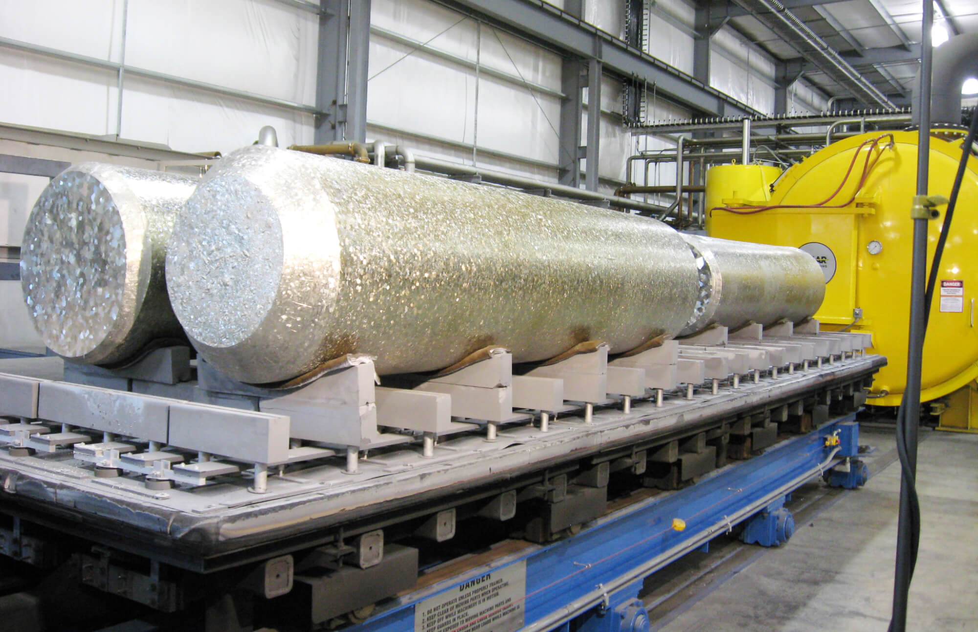
1. Kaowool Barrier: Typical load of Titanium logs on Kaowool with graphite fixturing. Processing temperature is 2350°F for 24 hours in high vacuum.
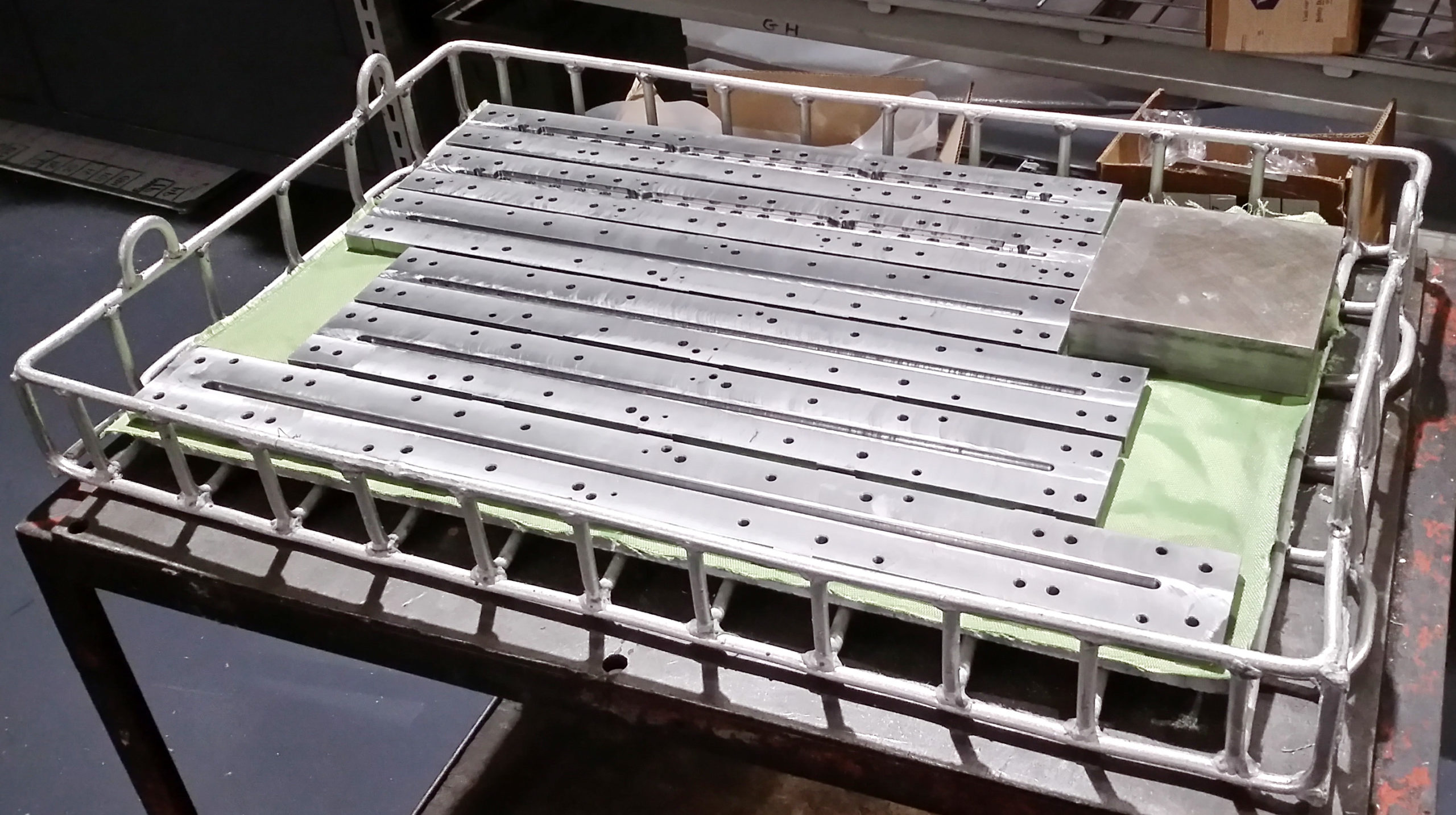
2. Refrasil Cloth Barrier: Separates the bars from the supporting graphite plate. This eliminates the possibility of a eutectic reaction when hardening the bars at 2125°F.
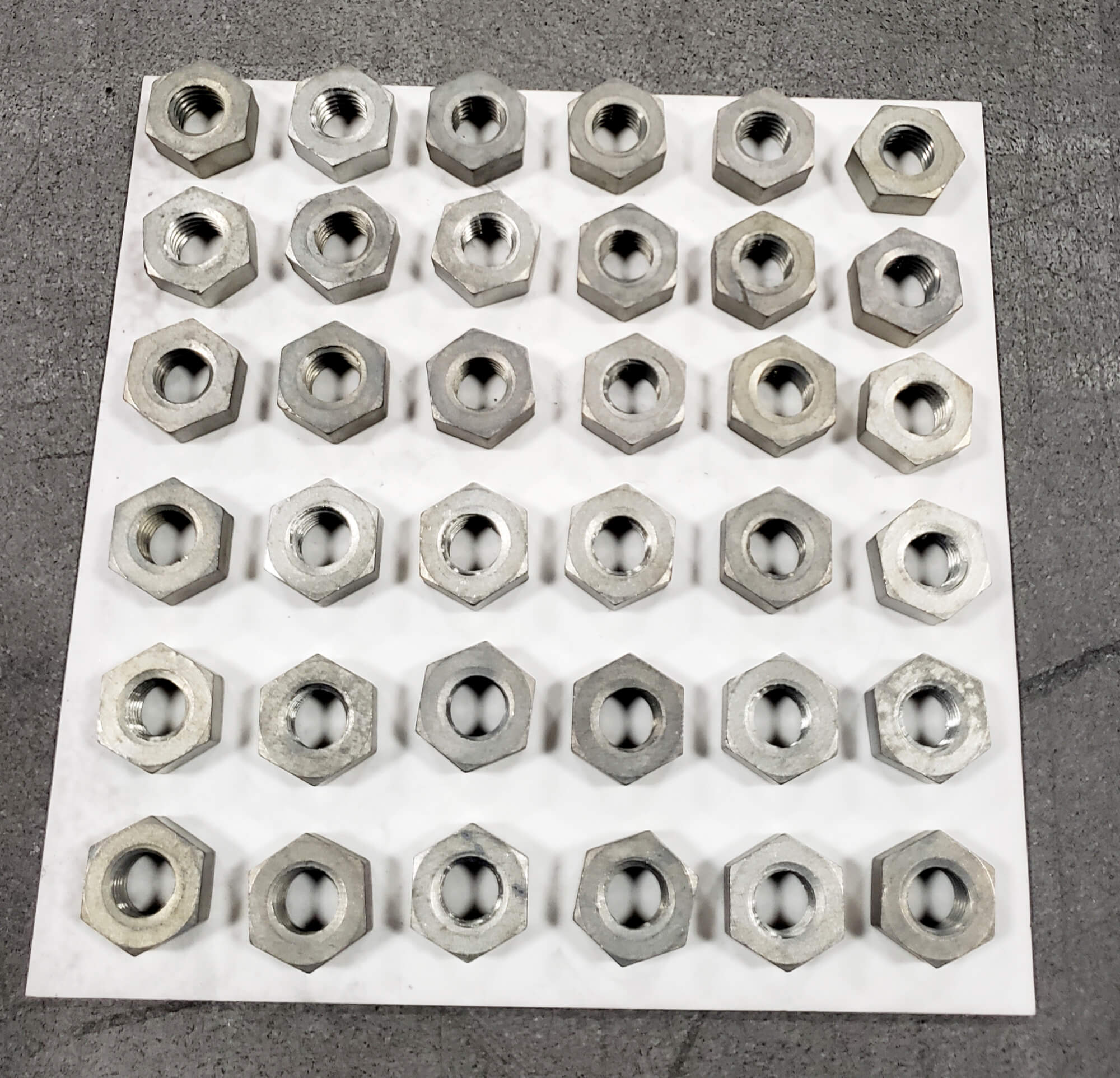
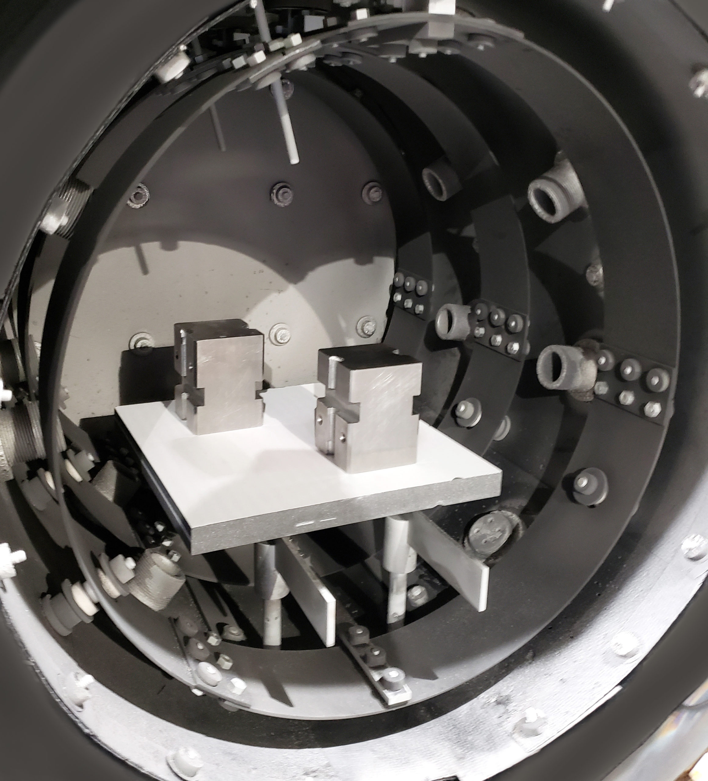
3. Ceramic Plate: Demonstrates the use of a thin ceramic plate to separate the fastening nuts from the graphite support plate. This process is for a sintering procedure to 2500°F.
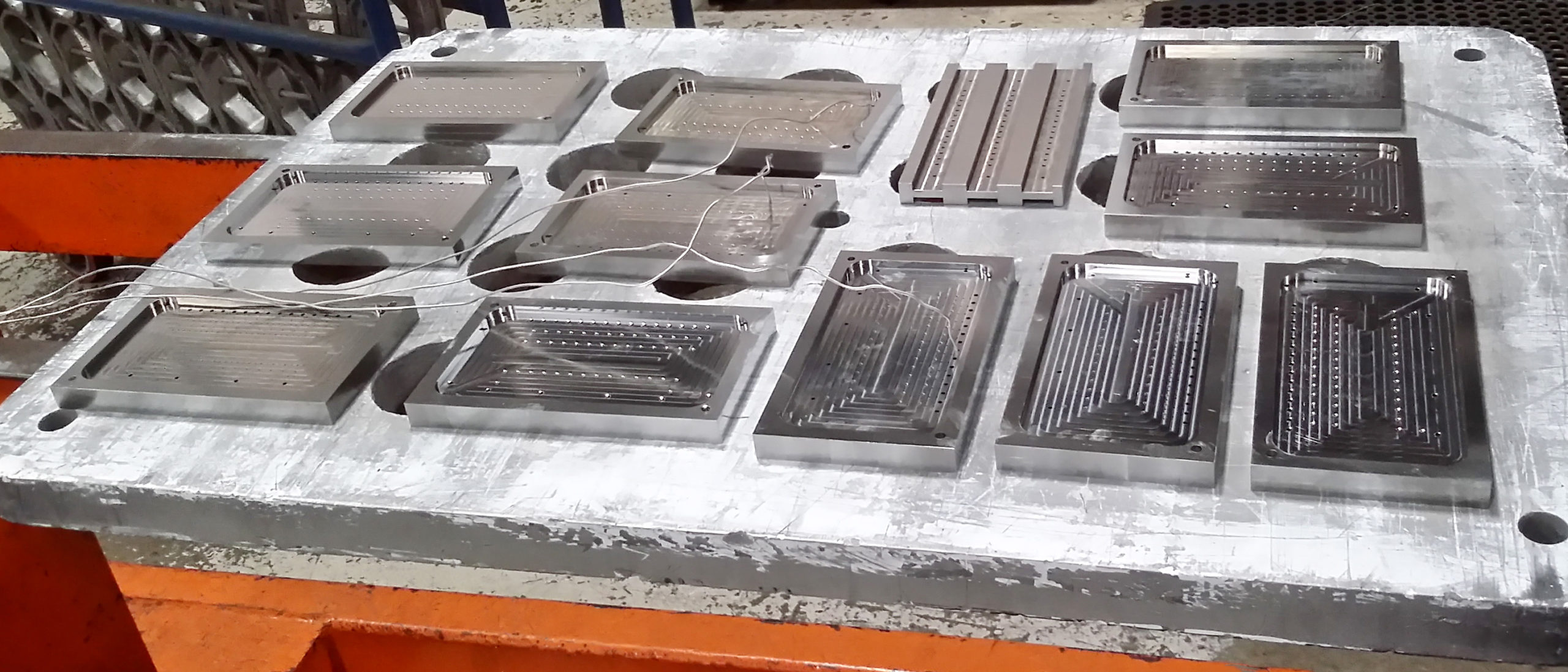
4. Ceramic Plate: Typical load of nickel iron alloy, MuMetal, fixtured on Alumina sheet with graphite support. Processing temperature is 2150°F.
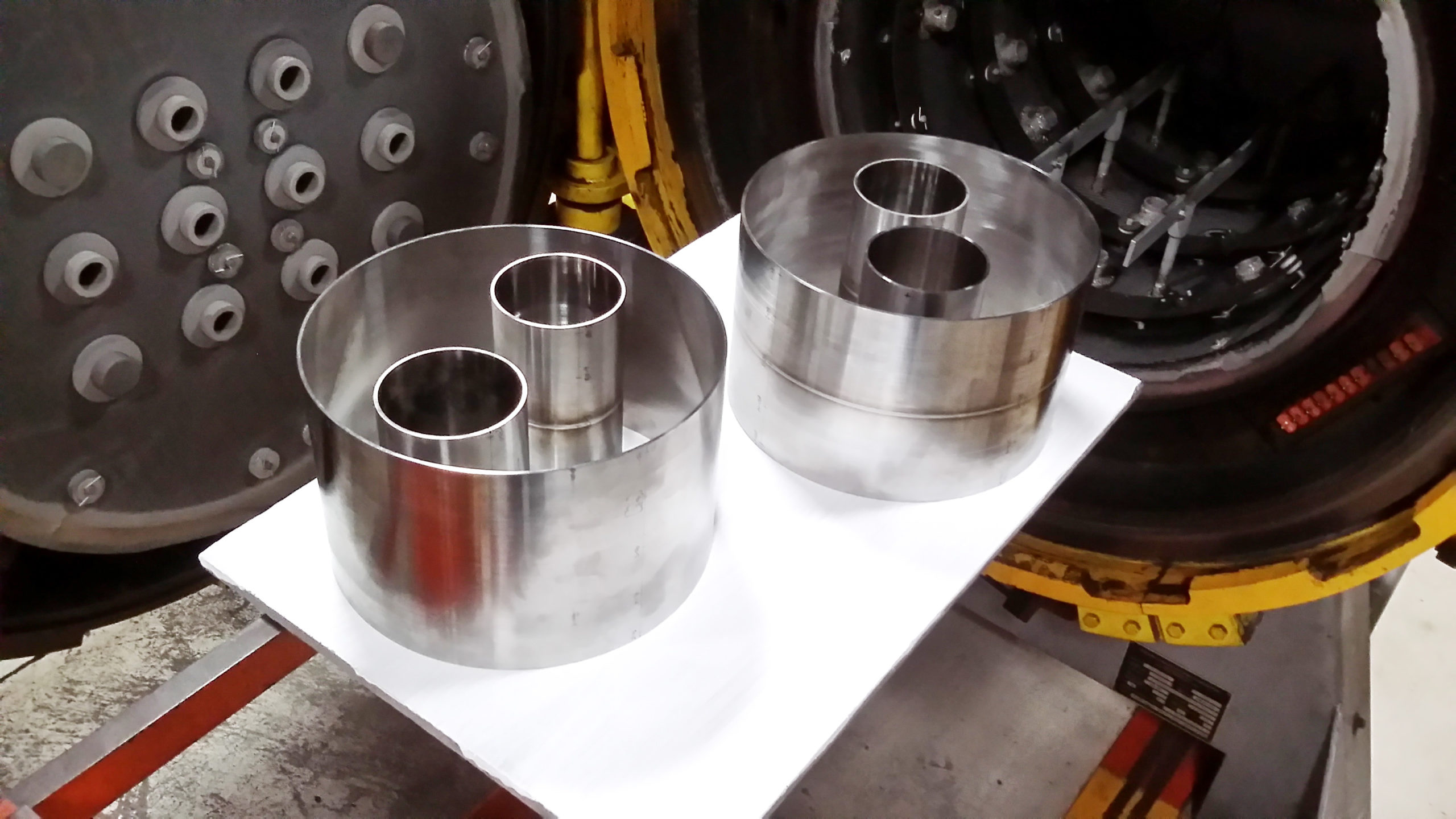
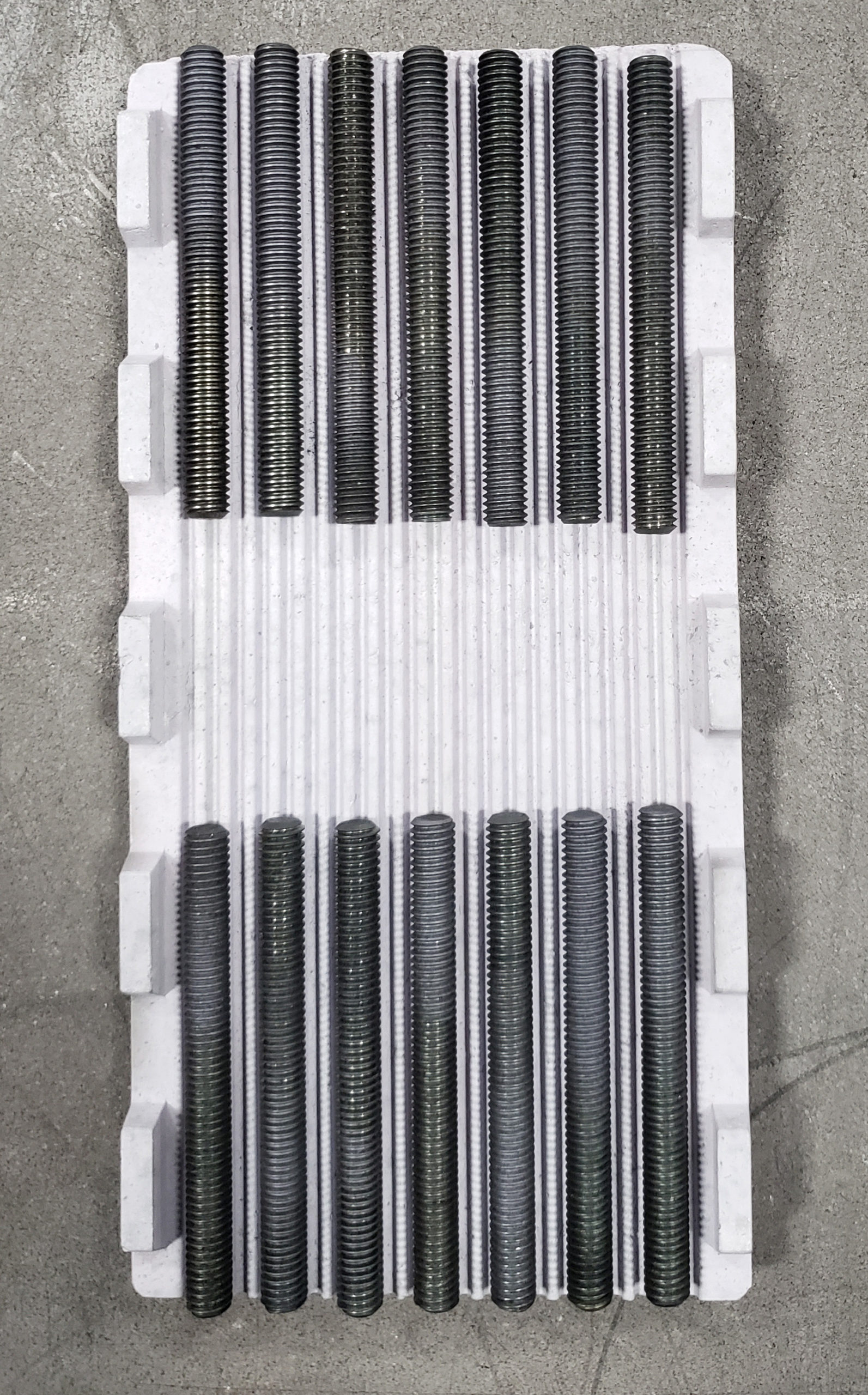
5. Ceramic Fixture: Using a special ceramic fixture to support the all-thread parts of high speed steel for a hardening cycle at 2100°F. The ribbed ceramic fixture separates the parts from the graphite support plate.
6. Stop-Off Barrier: Typical load of 420 stainless steel molds processed on graphite plate utilizing Wall Colmonoy Inc. white stop-off. Processing temperature is 1900°F.
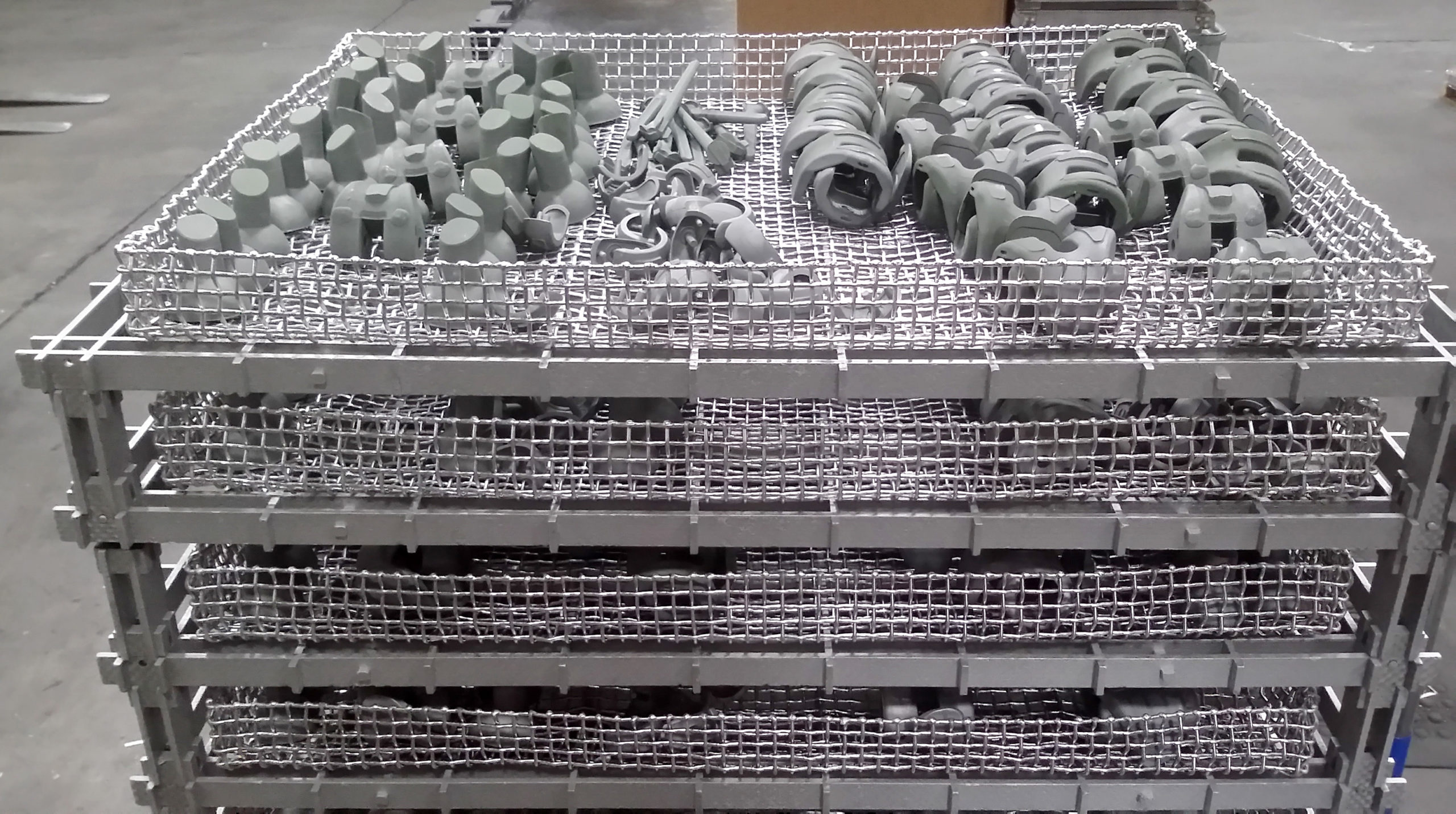
7. Green Stop-Offs: Typical load of orthopedic implants fixtured with alloy 330 screens utilizing Wall Colmonoy stop-off fixtured in CFC grids. Processing temperature is 2175°F.
8. Other Barrier: Graphite plate supporting the load separated by a high temperature aluminum barrier developed by GMI.2 This barrier would be similar to using the green stop-off material. This particular hardening process has an upper temperature of 2200°F.
These are just a few examples of how barriers are used to eliminate the possibility of eutectic, or sticking, reactions from forming.
We hope this document illustrates to the vacuum processing personnel how various forms of eutectic melting or sticking can be eliminated and how various types of barriers can be incorporated into a thermal treating process. For additional information, contact Roger Jones at roger@solaratm.com.
Also, check out our detailed booklet on critical melting points.
Written by: Real J. Fradette, Senior Technical Consultant, Solar Atmospheres, Inc., Roger A. Jones, FASM, CEO Emeritus, Solar Atmospheres, Inc.
References:
- Critical Melting Points and Reference Data for Vacuum Heat Treating Sept 2010, Solar Atmospheres, Inc.
- Graphite Machine Inc., Topton, PA
