Understanding Vacuum Furnace Temperature Measurement Issues
The objective of this paper is to provide technical information relating to vacuum furnace temperature measurement issues covering the following subjects:
- Thermocouple Construction
- Types of Thermocouples
- Vacuum Furnace Control Thermocouple Placement
- Temperature Uniformity in a Vacuum Furnace
- Use and Placement of Work Thermocouples
- How Work Material Properties Affect Heating Rates – Emissivity, Surface Finish, Mass, Surface Area
- Using Thermocouple Dummy Blocks and Their Placement
- Non-electrical Temperature Monitoring Devices
Thermocouple Construction

A thermocouple is normally defined by its’ junction type. These include as shown in Figure 1:
- Exposed Junction (Bare Wire) has the fastest response time – ideal for measuring rapid temperature changes.
- Ungrounded Junction (Sheathed) has a welded junction – insulated from the protective sheath and is electrically isolated. Longer in response time.
- Grounded Junction (Sheathed) has a junction welded to tip of sheath. Wires are completely sealed from contaminants. Good response time.
Note: Sheathed thermocouples with a small diameter have a faster response time while larger diameter sheathed thermocouples have longer life and are better for measuring higher temperatures (heavier gauge internal TC wire).
The sheath material of a thermocouple is based on application and temperature range requirements. Typical thermocouple sheath materials include:
- Inconel® 600 Sheath is ideal for severely corrosive environments and elevated temperatures. It resists progressive oxidation. Maximum operating temperature: 1148°C (2100°F).
- 304 SS Sheath is for general-purpose use, is corrosion-resistant, and good for general heat treating applications. Maximum operating temperature: 1148°C (2100°F).
- 316 SS Sheath has higher corrosion resistance than 304 SS. Withstands some strong acids. Maximum operating temperature: 1148°C (2100°F).
Types of Thermocouples
There are many types of thermocouples and based on the type of wire alloys used, they are defined by an ANSI Type Symbol. Our next chart (Figure 2) highlights the most common types used in vacuum furnace applications.

Further defining the additional characteristics of the above thermocouple types, we have:
- Type K – is used protected or exposed in in oxidizing, inert or dry reducing atmospheres; exposure to vacuum limited to short time periods; reliable and accurate at high temperatures
- Type N – is used protected or exposed in oxidizing, inert or dry reducing atmospheres; very reliable and accurate at high temperatures
- Type S – Normally used as control and over-temperature thermocouples with alumina protection tubes; very reliable and accurate at high temperatures
- Type W3 – Normally used for control of very high temperature applications; offers the advantage of ductility over pure tungsten thermocouples; Accurate at extremely high temperatures
Vacuum Furnace Control Thermocouples and Their Placement
Most vacuum furnaces in operation today use a Type S TC for Control and Over-temperature protection. They are rigid and normally with an Alumina (Mullite) Sheath. They are quite fragile and must be handled with care. See Figure 3 below.
The Type S TC is typically used in operations up to 2800oF. For higher applications, a Type B TC can be used for operations to 3200oF or a Type W3 for higher temperature applications.

The placement of the control TCs within the vacuum chamber is most critical. Using proper vacuum seals on the TCs to penetrate into the chamber, they must extend into the hot zone, a minimum of 2.5 – 3.0 inches beyond the heating elements of the furnace to minimize the effect of the heating element on the TCs.

The adjacent photo (Figure 4) illustrates a typical furnace with three zones of heating with a control TC penetrating beyond the elements at each zone and an over-temperature TC in the center also extending beyond the elements.
Temperature Uniformity in a Vacuum Furnace
In order to produce acceptable work in a typical vacuum furnace, it is essential that the furnace meet certain temperature uniformity standards within the hot zone area. The uniformity standard per ASM-2750E provides for class designations based on the acceptable uniformity for the class. The uniformity tolerances by furnace classes are:
- Class 1 – +/- 5oF
- Class 2 – +/- 10oF
- Class 3 – +/- 15oF
- Class 4 – +/- 20oF
- Class 5 – +/- 25oF
- Class 6 – +/- 50oF
Most vacuum furnaces are horizontal in configuration and a temperature uniformity survey (TUS) to meet the testing requirements required by ASM-2750E typically use a minimum of nine (9) TCs.
AMS 2750E allows for the use of racks specifically designed to accomplish the placement of the thermocouples for the TUS. A thermocouple heat sink attached to the rack is allowed for the thermocouple provided that the cross-section of the heat sink does not exceed 0.50” or is not thicker than the thinnest material being processed. The key to any rack structure is to be able to correctly place and rigidly support the T/Cs at the true dimensions of the furnace work zone.
Racks can be specifically designed as they apply to the expected use of the vacuum furnace. Also, baskets can be stacked to represent a full load configuration with the T/C heat sinks positioned on the on the inner eight corners of the baskets with a ninth T/C positioned in the center position of the load.
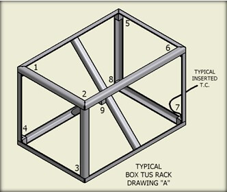
Solar has designed several T/C racks similar to the image shown in Drawing A (Figure 5). Typically this is a box configuration fabricated using stainless steel angle members with heat sink blocks located at the corners and center position. This structure will satisfy many commercial applications but has certain limitations when conforming to AMS 2750E and is not universal for multiple sized furnaces all requiring TUS.
Also, these types of racks require considerable storage space when not in use.

The newest, most acceptable and universal TUS support structure that has been designed, consists of individual stainless steel corner pipe members that sit vertical with a bottom support structure (Figure 6). The vertical height of each member can be adjusted with different center lengths to accommodate various size furnace hot zones. Each structure can be accurately positioned to the outer extremes of the hot zone to locate the eight corner T/Cs. An additional center structure is provided to properly locate the center T/C. All main pipe corner vertical structures will have top and bottom T/C heat sinks welded to the inner surface. Each heat sink may be 1/2” diameter by 3” long with a hole drilled on center to accept the T/C. This type of support structure configuration should be used to meet the most critical aerospace applications.
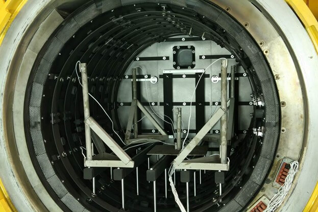
Our photo to the right (Figure 7) illustrates our rack structure positioned in the furnace ready to initiate a temperature survey.
The survey frequency on any furnace is dependent on the furnace class. The following frequency of TUS shall be required:
Class 1 & 2: An initial survey performed prior to production followed by three monthly periodic surveys for a total of four as the initial frequency. Subsequent surveys may then be reduced to quarterly provided prior surveys are all acceptable.
Classes 3 – 6: An initial survey performed prior to production followed by three quarterly periodic surveys for a total of four at the initial frequency. The frequency may then be reduced to semi-annually provided all prior surveys are acceptable.
Use and Placement of Work Thermocouples
Work Thermocouples
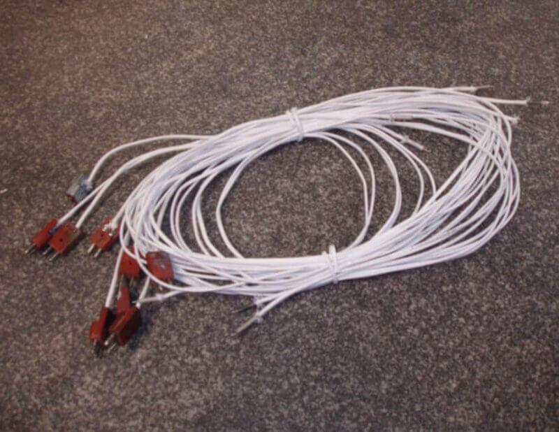
Work thermocouples (Figure 8) measure heat transfer from heating elements to the “work”. They are typically placed in or on the part being processed.
The factors affecting heat transfer include:
- Thermal conductivity of the part.
- Emissivity/absorptivity of the part.
- Mass of the work load
- Surface area of parts
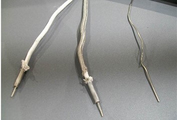
Typical work thermocouples are shown in the adjacent photo (Figure 9). From left to right, these would include:
- A bare wire with an alumina sleeve covered with a Refrasil sheath. Tip is ½” hard twist.
- A bare wire with an alumina sleeve covered with a Stainless Steel Mesh. Tip is ½” hard twist.
- This is a 1/16” Inconel sheathed TC.

Most work thermocouples (Figure 10) used in vacuum furnaces are:
- Type K – most common and least expensive yet very accurate. Currently losing favor to Type N.
- Type N – tends to now show improved accuracy and seems to provide extended life and multiple re-use.
- Both of the above are a concern on re-use when having operated over 2150oF as they tend to drift.
- Aerospace industry requires new Type K thermocouples after each run.

Most vacuum furnaces incorporate an internal work thermocouple jack panel (Figure 11) positioned outside the furnace hot zone. This eliminates the need to continually provide a good vacuum seal into the vacuum chamber for the thermocouples.
The jack panel can be a source of error and must be cleaned regularly. In addition, any TC jacks that are not used during a particular cycle should be sealed with dummy plugs to eliminate contamination.
Placement of Work Thermocouples
Since the configuration of a workload typically varies with each cycle, it is essential that the thermocouples be placed in the optimum position to reflect the accurate temperature of the workload. Basic rules on placement of the TCs would be:
-
Figure 12 Place the load thermocouples in existing holes or crevices with the tip or hot junction in contact with the metal.
- Work thermocouples must be inserted deep into the center of the workload, especially on dense loads. (Figure 12)
- Consider an area on the workload that is most shielded from the radiation or the thickest cross-sectioned part in the load (slowest portion to reach equilibrium.
- Our example to the above illustrates TCs deeply imbedded during the annually process for brass tubing.

Our two photos to the right (Figures 13 & 14) demonstrate workloads that are difficult to thermocouple. These require that the thermocouples be fully imbedded into the center of the load.

Examples of load that are poor conductors of heat would be:
- Loosely coiled and stacked sheet
- Loosely rolled screen
- Loosely coiled wire
- Small fasteners/ ball bearings
- Powders
Common workload thermocouple problems could include the following:
- Crossed wires: If a thermoelectric circuit is backwards, the instrument will read backwards.
- Loose screw: A loose screw on the mounting plug will cause a poor connection and possibly shorting.
- Uncompensated junction: If materials are used that are not the same as the wires, an error will be introduced.
- Twisted wires: If wires touch at a point between the hot and cold junctions, a new hot junction will be produced causing a measuring error.
- Damaged insulation: If the insulation is damaged, and wires touch foreign materials, an error will be introduced. In addition, this easily allows twisted wires to touch.
- Poor hot junction: A loosely twisted or dirty junction will introduce an error.
- Dirty jack panel or extension wires: A dirty jack panel is a typical source of error and must be cleaned regularly.
How Work Material Properties Affect Heating Rates – Emissivity, Surface Finish, Mass, Surface Area
The ability of a part or material to accept heat at a certain rate is based on several factors. These include:
- Emissivity – The ability of a surface to emit radiation
- Absorptivity- ability of a surface to absorb radiation
- At thermal equilibrium, the emissivity of a body (or surface) equals its absorptivity
- A perfect black body (absorbs 100% radiation)
In order to demonstrate the above factors we created a test study. The test included preparing six (6) same sized dummy blocks of various surface conditions (Figure 15 below) and then subjecting them to the same heat treat cycle to record the heating profiles. The blocks were 2.5” cubes of carbon steel with the surface modified or plated as shown in our next photo. A thermocouple was inserted half way down the center of each block.

The blocks were first heated to 1000oF, held for four (4) hours and then heated to 1700oF and held for one (1) hour. The curves below (Figure 16) illustrate the serious time difference for the various blocks to reach temperature.

Using Thermocouple Dummy Blocks and Their Placement
There are many workloads that are processed in a vacuum furnace that do not allow for work thermocouple to be placed in or in proper contact with the parts. This leads us to the introduction of dummy thermocouple blocks placed in the furnace to simulate the workload.
Based on our prior study illustrated above, when preparing or manufacturing dummy blocks, the following rules should be observed.
- Drill TC holes into center of the block.
- Match cross-section to largest workload part.
- Match the mass of the work
- Match thermal conductivity
- Match the surface condition
- Match emissivity
- Match the material of the parts
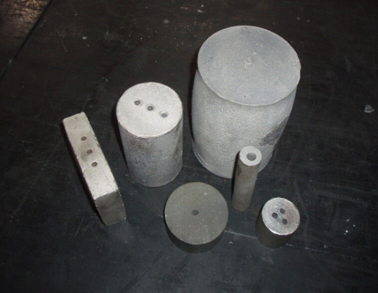
Our photo to the right (Figure 17) shows various dummy blocks used in varying load configurations.

Often it is not practical to produce a dummy thermocouple block to be an exact duplicate of the workload parts. An example is shown to the right (Figure 18) where the dummy block represents approximately one third of the actual parts height. However the critical cross-section dimensions have been simulated to represent true heating rate.
Some conclusions relating to the use of thermocouple dummy blocks would be:
- Radiation heating of work is dependent on mass and surface condition
- Heat rate : Bright and polished much slower than dull and dark
- Rough surfaces heat faster than smooth, reflective surfaces
- Dummy blocks not in direct contact with parts must have similar mass and surface area to mimic the heat rate of load
- Dummy blocks should be periodically re-conditioned to maintain proper surface smoothness and appearance
- One load of material, with a particular surface condition, compared with a load of the same material with another surface condition, could take as much as twice as long to reach the desired temperature
Non-electrical Temperature Monitoring Devices

Recent and new developments have produced some interesting alternatives to work thermocouples to measure part temperature in a vacuum furnace. The latest is an easy and cost effective method to monitor process temperature – Orton Temp Tabs (Figure 20).
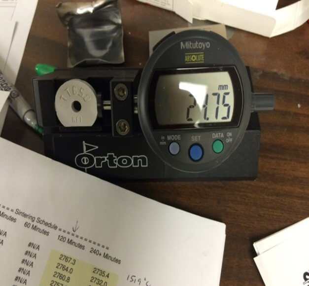
What are Orton Temp Tabs? They are ceramic disks that sinter at a controlled rate over a range of temperatures. The shrinkage is then correlated to the maximum temperature reached in the furnace. Therefore, they record peak temperature only.
Using and Measuring Temp Tabs
-
Figure 21 Temp Tabs are measured after they exit the thermal process (Figure 21).
- Best accuracy is achieved using a Temp Tab desktop gauge.
- Place the Temp Tab in the gauge and measure the diameter.
- Other measuring devices can be used as long as they measure to .01 mm.
- Enter the diameter measured into the Temp Trakker software or look up the temperature on a printed chart.
A typical Temp Tab chart (Figure 22) to correlate the exact temperature provided by the tab shrinkage dimensions is shown to the right.
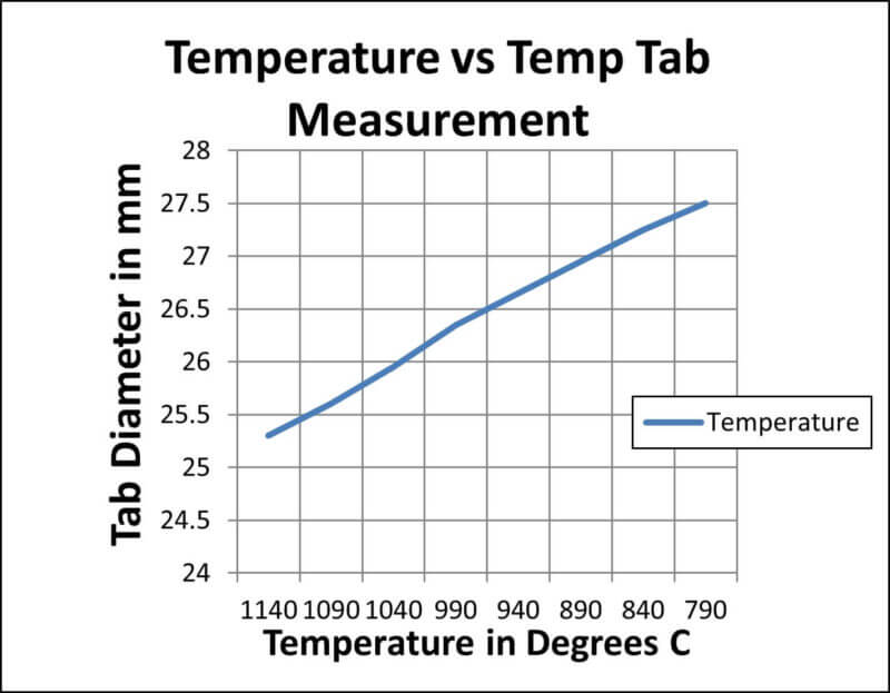
Although Temp Tabs only record peak temperature, they can still be useful in a vacuum furnace to confirm thermocouple readings and feedback.
Conclusions
As has been highlighted above, the accurate measurement of temperature within a vacuum furnace can be a fairly complicated subject. Summarizing critical areas, we have:
- Both control and work thermocouples must be positioned properly to accurately reflect the true temperature conditions of the furnace and the workload.
- The type of thermocouple used is dependent on the temperature range and the application.
- Different types of sheathed thermocouples react at different heating rates based on their construction.
- Furnace temperature uniformity requirements are based on the Class type and application per ASM-2750E.
- Workload heating rate is determined by several factors including cross-section, mass, emissivity, surface condition and material being processed.
- When using dummy thermocouple block to represent the workload, it is essential that the dummy block be designed to satisfy all the factors in our prior paragraph.
- Temp Tabs can be useful in certain applications to measure and confirm peak furnace temperature.
Written By:
- Real J. Fradette – Senior Technical Consultant – Solar Atmospheres Inc
- Virginia M Osterman – Ph.D. Senior Scientist – Solar Atmospheres Inc
- William R. Jones – CEO – Solar Atmospheres Inc
