Vacuum Gas Cooling – Is Pressure or Velocity Most Important? (Part 1)
Introduction
There is an age-old adage that exists in the heat treating world. That supposition states that “the smaller the vacuum furnace, the faster it will quench.” Our study compared the cooling rates of two distinctly sized High Pressure Gas Quenching (HPGQ) vacuum furnaces- a large 10-bar vacuum furnace equipped with a 600 HP blower motor versus a smaller 10-bar vacuum furnace equipped with a 300 HP motor. Both furnaces, one with 110 cubic feet, the other with a 40 cubic foot hot zone respectively, were exclusively engineered and manufactured by Solar Manufacturing located in Sellersville, PA.
History
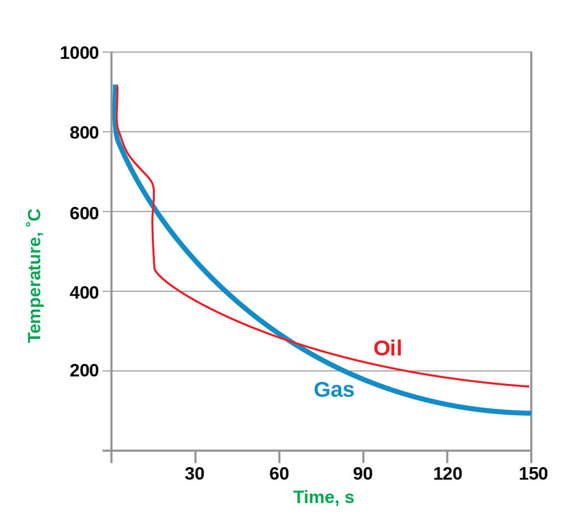
High Pressure Gas Quenching in the heat treatment of metals has made tremendous strides over recent years. Varying gas pressures within the chamber have been shown to be more governable than their oil and water quenching counterparts. The number one benefit of gas cooling versus liquid cooling remains the dimensional stability of the component being heat treated. In addition, using gas as a quench media mitigates the risk of crack initiation a component dramatically. This is primarily due to the temperature differentials during cooling. Gas quenching cools strictly by convection. However, the three distinct phases of liquid quenching (vapor, vapor transport and convection) impart undo stress into the part causing more distortion (Figure 1).
There are multiple variables involved with optimizing gas cooling. These include the furnace design, blower designs, heat exchanger efficiency, gas pressure, gas velocities, cooling water temperatures, the gas species used and the surface area of the work pieces. Whenever these variables remain constant, the relative gas cooling performance of a vacuum furnace typically increases as the volume of the furnace size decreases.
The Furnace
Solar Manufacturing has built multiple high pressure gas quenching furnaces of varying sizes over the years ranging from 2 to 20 bar pressure. We have learned that vacuum furnaces, rated at 20 bar and above, became restrictive in both cost constraints and diminishing cooling improvements. Therefore, Solar Manufacturing engineers began to study gas velocities to improve cooling rates. They determined that by increasing the blower fan from 300 horsepower to 600 horsepower, along with other gas flow improvements, would substantially increase metallurgical cooling rates. The technology was reviewed and was determined to be sound. A 48” wide x 48” high x 96” deep HPGQ 10-bar furnace equipped with this newest technology was purchased by Solar Atmospheres of Western PA located in Hermitage, PA.
The Test
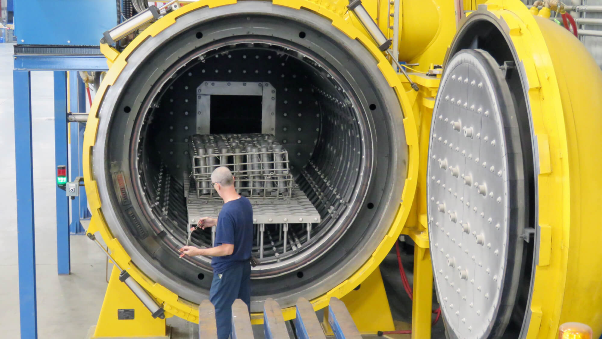
Once this new vacuum furnace was installed, a cooling test was immediately conducted. A heavy load would be quenched at 10-bar nitrogen in an existing HL 50 sized furnace (36”x 36” x 48”). The same cycle was repeated in the newly designed vacuum furnace almost three times its size! (See Pictures 1 and 2)
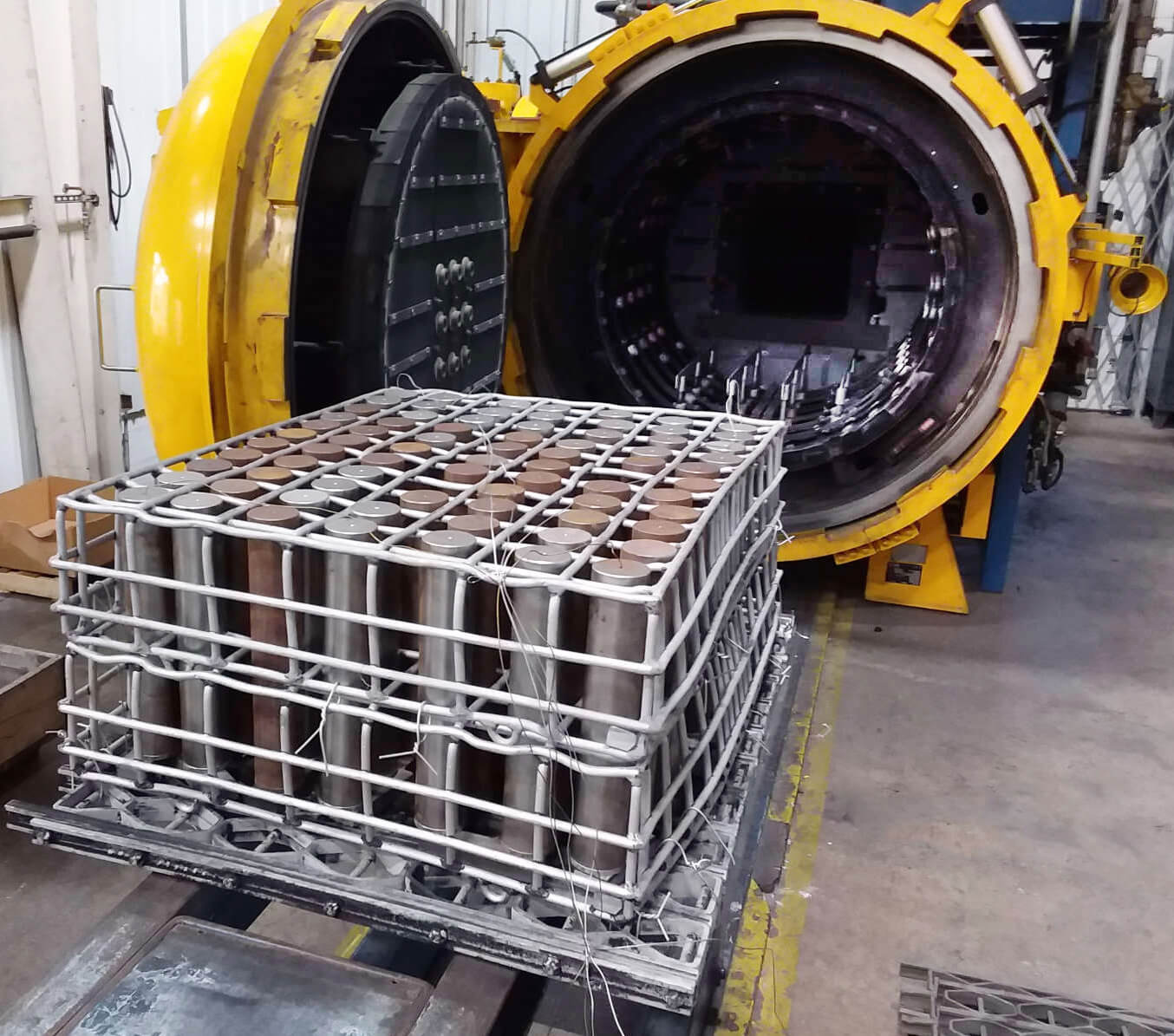
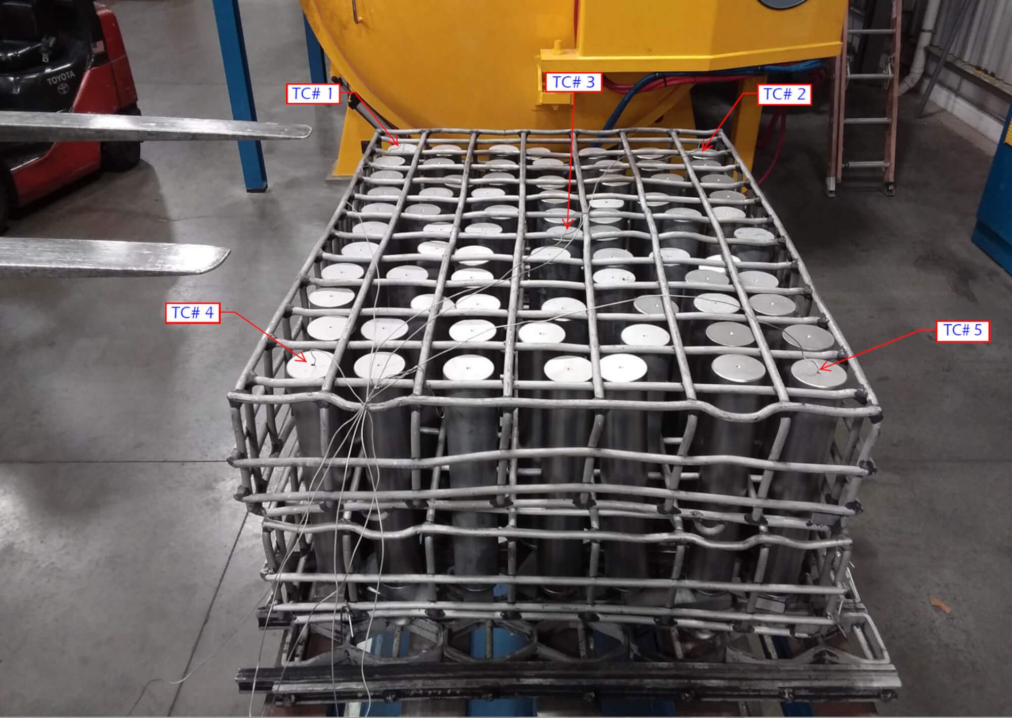
The load chosen for the experiment was 75 steel bars 3” OD x 17” OAL weighing 34 pounds each. The basket and grid system supporting the load weighed 510 pounds. The total weight of the entire load was 3,060 pounds. Both test runs were identically thermocoupled at the four corners and in the center of the load. All five thermocouples were deeply inserted (6” deep) into ¼” holes at the end of the bars (See Picture 3). Each load also contained two 1” OD x 6” OAL metallographic test specimens of H13 hot working tool steel. These specimens were placed near the center thermocouple to ensure the “worst case” in terms of quench rate severity. All tests were heated to 1850°F for one hour and 10-bar nitrogen quenched.
Results
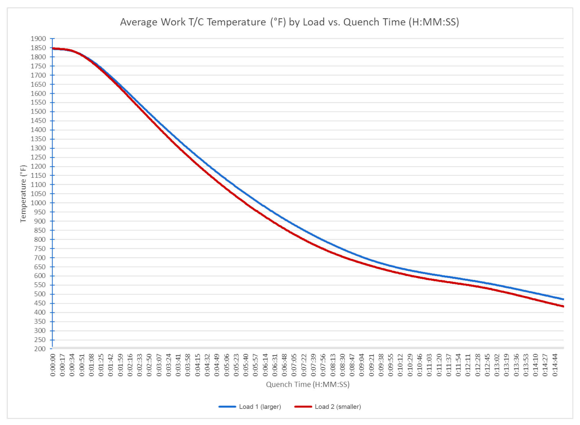
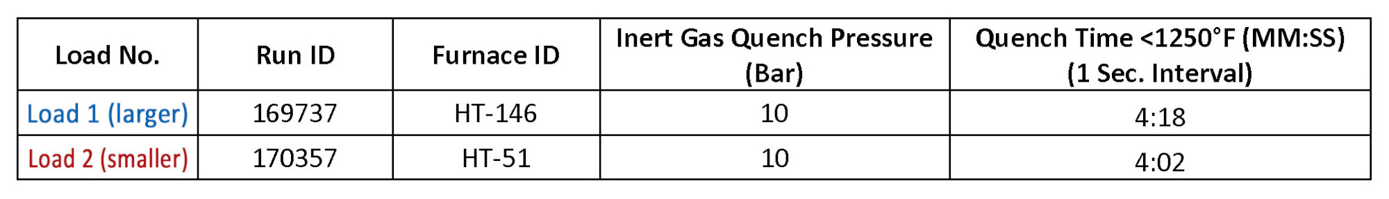
The comparative cooling curves between both HPGQ vacuum furnaces are shown in Chart 1. Table 1 reveals that in the critical span of 1850°F to 1250°F for H13 tool steel, the cooling rate in the larger furnace with more horsepower nearly matched the cooling rate of the furnace was three times smaller in size.
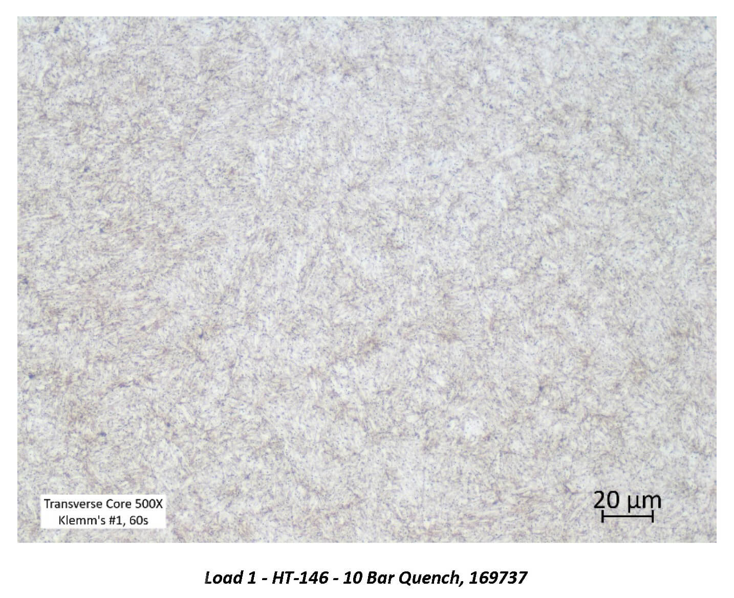
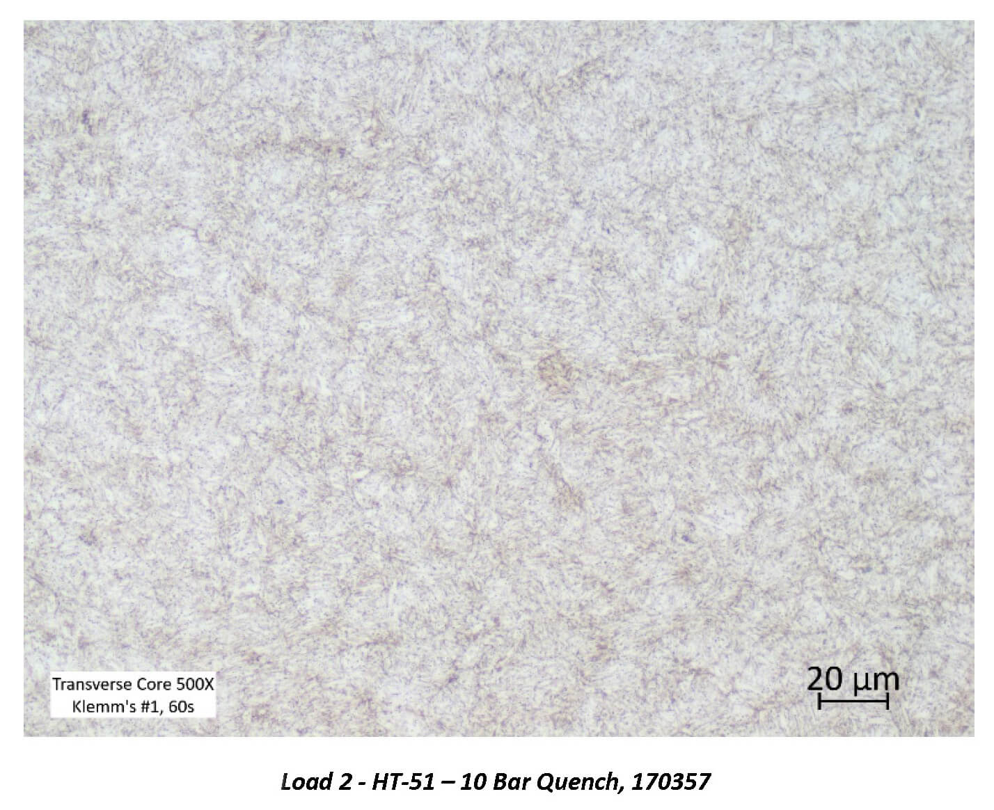
Micrographs of the H13 test specimens processed in each load were prepared (Pictures 4 & 5). The microstructure of each test specimen is characterized by a predominantly tempered martensitic microstructure with fine, undissolved carbides. The consistency of the microstructure across both trial loads further demonstrates that while the larger furnace utilized the higher horsepower, both resulted in a critical cooling rate sufficient to develop a fully martensitic microstructure.
Conclusions
These tests prove that the greatest impact on the cooling performance in a vacuum furnace is to increase the gas velocity within that chamber. This was achieved primarily by increasing the horsepower of the blower fan. By doing this, the ultimate cost to the customer is significantly less than manufacturing a higher pressure coded vessel. This newly designed vacuum furnace has proven to be a game changer.
Part II of this article will discuss real life case studies and how both Solar and Solar’s customers have mutually benefited from this newest technology.
Written by: Robert Hill, FASM, President, Solar Atmospheres of Western PA
Gregory Scheuring, Plant Metallurgist, Solar Atmospheres of Western PA